To help
water parks avoid troubles caused by incomplete supplies and unprofessional
support services, prevent project delays, and enable timely, safe and orderly
park operations, Guangdong H-Fun provide one-stop water park supplies solutions for water parks and one-on-one problem-solving support. We are committed to delivering
time-saving, energy-saving, cost-effective and worry-free one-stop professional
services to many water parks worldwide.
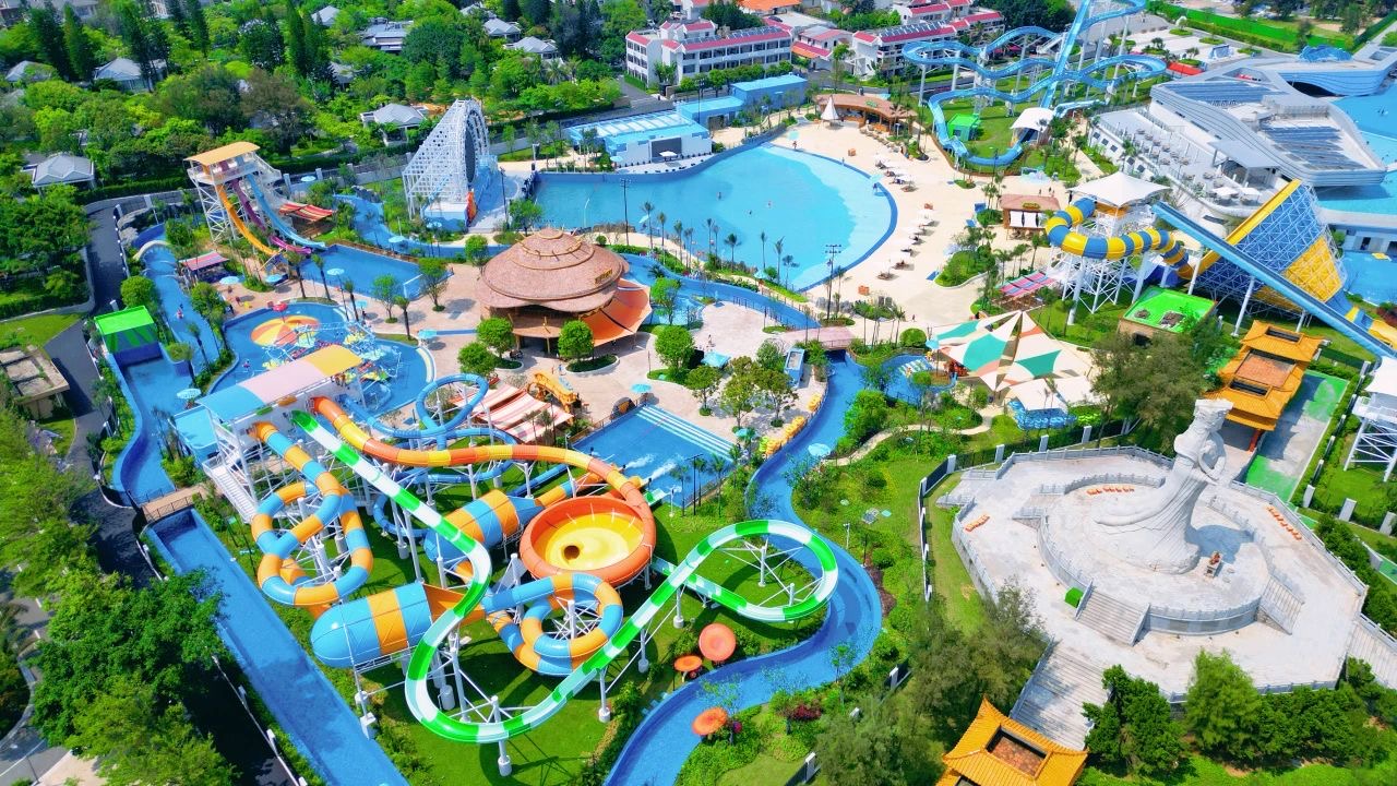
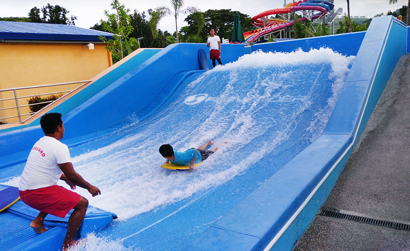
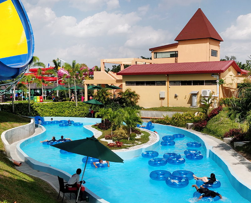
For example, Aqua Planet is one of the largest water parks in Philippines, with total area
of 10 ha, in which the area of wave pool reaches 3500 m2 and
length of lazy river exceeds 400m. Designed by Aquatic Development Group(ADG), some slides are rather extreme like Tornado、Aqua Loop、Super Bowl、Octopus Racers etc. They looked for Guangdong H-Fun for one-stop solution.
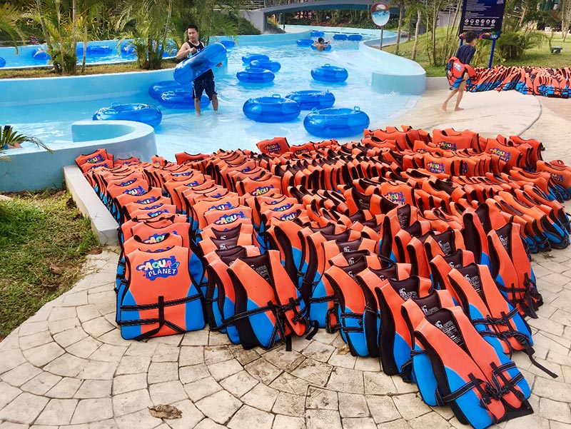
We made full allocation according to the drawing
of the park, we provided 1300pcs of single and double tubes for lazy river and
wave pool, and corresponding life jackets. Together with cloverleaf tubes,
water slide mats and surf board etc.
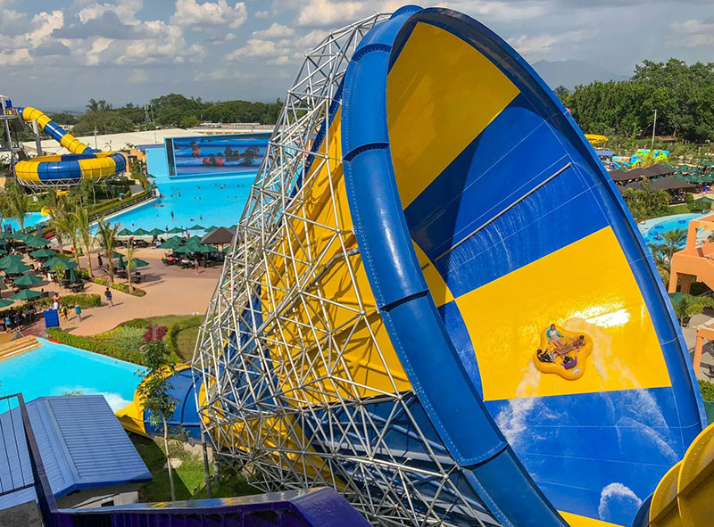
We
communicate with designer and supplier of water slides closely, to make and
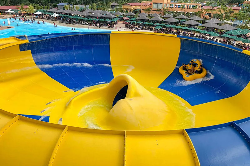
test most suitable vehicles of these slides. For example, cloverleaf tubes with funnel
shape seat hole for Tornado and Super Bowl slide, Players can slide safely and
comfortably from the 16m high platform, plunge and swirl like like in tornado
and super bowl.
All our tubes sealed by Smooth reinforced
overlap heat bonding, can not damage at the joint. All tubes tested 24 hours
before delivery, to ensure safety and confortable on the slide. Our mats have
extra layer material cover handle screws, can not tear off at handles part, much
safer and can use much longer time.
We provided
high quality body boards and stand boards for surf pool, firm EVA foam rescue
tubes, 9cm diamter spiral type swimming pool lane lines, and inflatable seasaw,
Saturn and icebergs etc.
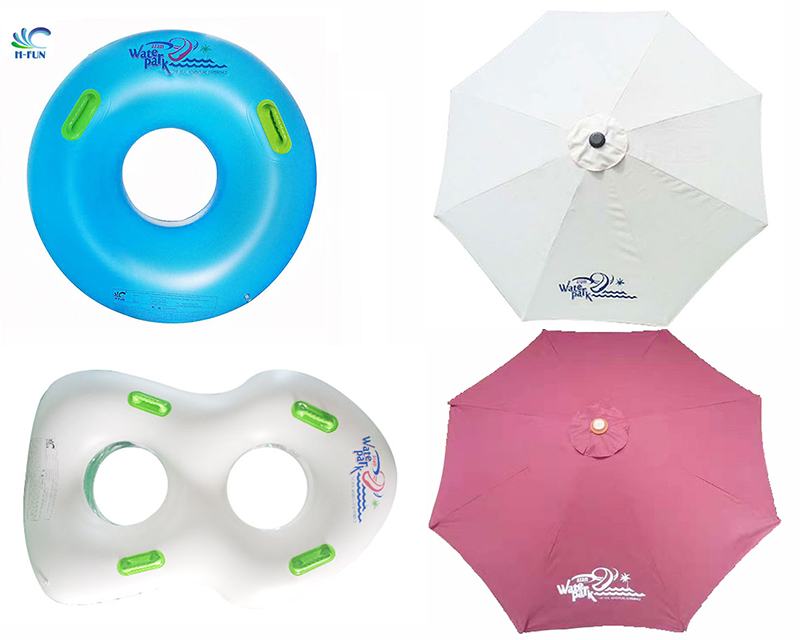
We made
customized print on all tubes according to logo design of the park, help them
to Became one of the largest
water park in Philippines, and one of well-known water park in
Southeast Asia.
Another example, Azam Water Park, located at Verde Hotel in Zanzibar, Tanzania,
officially opened in December 2019, is the only water park on the island. Supported by Whitewater West, Verde Hotel Zanzibar intended to Create a“unique,
attractive water park”for tourists and local citizens.
We provided 500 pcs of single and double tubes, including exclusive iceberg design tubes according to the park’s theme and hotel style, with
customizable logo and color matching.
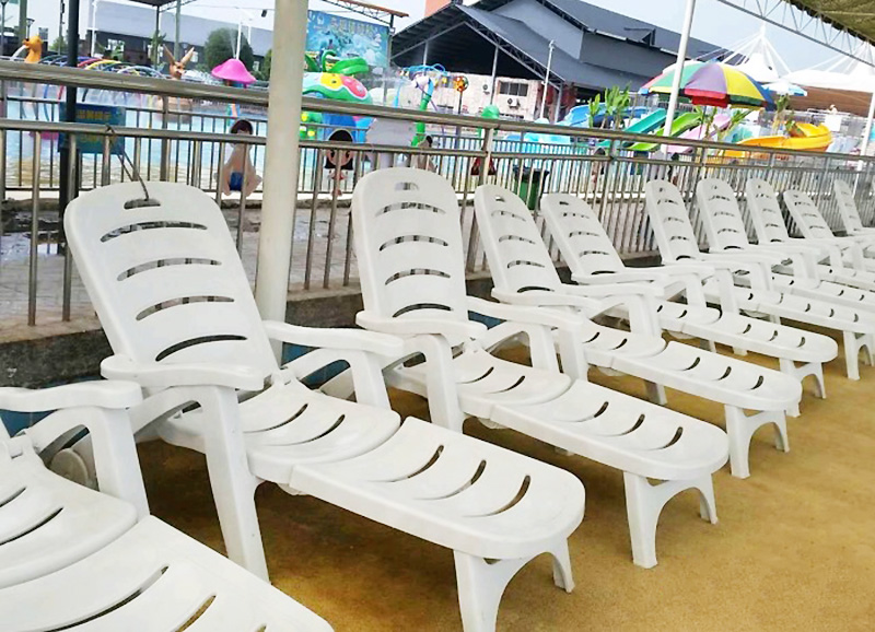
We send 2 containers of top quality water park tubes, pool cleaner & lifesaving products, including pool brushes, leaf skimmers,
life guard seats, life buoys, rescue tubes, rescue hooks, rescue ropes and Outdoor Furniture like sun loungers, parasols, table and chairsetc. we printed the park logo
on each parasols.
We optimized structure designs including foldable loungers and table and
chairs, foldable parasol and life guard seats, to save space and shipping cost. Most of products already used many years since the opening of the park.
In professional production, the stage truss is the skeleton that holds the entire show together. It isn’t just a technical specification on a blueprint; it is a decision that dictates how many stagehands and forklifts you need to hire, and how much weight it can actually handle.
For years, there has been a hot debate among people about whether to stick with the "heavy-duty" traditional steel truss or embrace the modular flexibility of aluminum truss. Neither material is a universal "winner" in every category. Instead, the right choice depends entirely on the nature of the project, whether it’s a mobile concert tour or a permanent high-capacity installation.
In this guide, we will break down the practical differences between an aluminum truss and its steel counterpart. If you are new to the world of stage rigging and want a foundational overview first, our introduction to stage truss systems is a good starting point before diving into this comparison.For those already familiar with the basics, we will get straight to what matters: the load capacity, the ROI, the labor costs, and the safety factors that actually make or break a decision when you are under a tight deadline and need a reliable stage truss setup.
Material Science: Aluminum vs. Industrial Steel
To understand the comparison, we have to look at the metallurgical properties of these structures. The performance of a stage truss starts at the molecular level.
The Engineering Behind Aluminum 6082-T6 and 6061-T6
In the professional rigging world, a high-quality stage truss is primarily made from aluminum 6061-T6 and aluminum 6082-T6. This is an "aircraft-grade" alloy that has been treated for maximum strength and hardness. The "T6" refers to the tempering process, which involves heat-treating the metal to create a material that is incredibly stiff. This alloy is the standard for a portable stage truss because it provides excellent structural integrity while remaining exceptionally lightweight. If you are unsure whether a spigot or bolt connection system suits your project better, our detailed breakdown of spigot vs. bolt aluminum trusscovers the key differences.
The Structural Profile of Galvanized Steel
Steel is the titan of the construction world. It is undeniably denser and offers a different kind of rigidity. To protect it from the elements, a steel stage truss must be galvanized or painted, which adds to its overall bulk. While this density is a disadvantage for touring gear, it is a massive asset for permanent stadium roofs or industrial grids where the structure will never move. In those cases, the sheer mass of steel provides a level of vibration dampening and long-term stability that aluminum cannot match.
The Weight Factor: Speed vs. Stability
Weight is the most impactful variable in event logistics. Depending on your business model, weight can either be your enemy or your greatest structural ally.
Transportation Costs and Freight Efficiency
An aluminum truss is roughly one-third the weight of a steel section of the same size. For a rental company hauling a massive stage truss roof across the country, this weight difference is a primary concern. Using aluminum allows you to fit more production equipment on a single truck before hitting weight limits. Conversely, if you are building a fixed installation where transportation is a one-time cost, the weight of a steel stage truss is less of a concern and may even be preferred for its heavy-duty feel.
Labor and Setup Speed: 2-3 Person Crew vs. Forklifts
Labor costs are a major part of any budget. As an aluminum truss is light, a two-person crew can usually carry and connect sections manually. This allows for rapid assembly in tight venue windows. If you are working with a steel stage truss, the physics change. You will likely need forklifts or material lifts just to move components into place. For a permanent stadium install, this extra labor is a small price to pay for the ultimate durability of steel. However, for a one-night corporate event, it can be a deal-breaker.
Load Capacity in the Modern Stage Truss Environment
The debate often centers on whether aluminum is "strong enough." The answer depends on the scale of the load and the span of the rig.
Meeting Professional Standards: LED Walls and Line Arrays
Modern event rigs usually consist of LED video walls and line-array speakers. A standard 290mm or 400mm aluminum truss is specifically engineered to handle these point loads. When you consult the certified load chart for a professional stage truss, you'll see that aluminum systems are more than capable of supporting professional production gear. However, for extreme spans such as a 50-meter roof over a stadium, the extra tensile strength of a steel stage truss becomes necessary to prevent excessive "sag" or deflection.
Safety Factors and Certified Load Tables
Safety is about staying within the calculated limits of your material. Both materials come with strictly tested load tables. As long as a rigger follows these charts and accounts for the required safety factor, both are equally safe. Aluminum provides a predictable visual warning by showing slight deflection before reaching its limit, whereas a steel stage truss remains very rigid right up until it hits its maximum capacity. For event pros operating in European markets, this safety behavior is one of the reasons why aluminum structures are increasingly specified under EN 1090-3 certification standards, which set strict requirements for the structural performance of aluminum components.
Durability and Weather Resistance (Indoor vs. Outdoor)
The environment you use it in will largely determine which material will last longer in your inventory.
Corrosion Resistance: Why Aluminum Wins for Events
Aluminum possesses a natural ability to fight off corrosion. As soon as the metal comes into contact with oxygen, it creates a microscopic oxide film that covers the entire surface. This barrier prevents moisture from reaching the core of the material. You can store aluminum in less-than-perfect conditions without worrying about structural decay.
Steel requires much more maintenance. If the paint or galvanization on a steel stage truss gets scratched in a warehouse, which is inevitable, the exposed iron will rust. Once rust begins inside the tube, it becomes a hidden safety risk. For this reason, steel is best suited for climate-controlled indoor venues or structures with high-quality permanent coatings.
Maintenance and Aesthetics
An aluminum stage truss maintains its "pro" silver look for a long time with minimal cleaning. Steel trusses often require regular repainting to remain presentable. If your clients are high-end corporate brands, they usually prefer the clean, metallic look of aluminum. If you are building a "black box" theater where the gear is hidden, the aesthetic upkeep of steel is less of an issue.
Calculating the ROI: Which Investment Makes Sense?
The purchase price of the material is only the starting point of the financial analysis.
Total Cost of Ownership (TCO) Comparison
When you calculate the "Total Cost of Ownership" over five to ten years, the results vary based on use.
For Rental Companies: Aluminum offers a faster ROI through lower labor and transport costs.
For Permanent Installs: Steel can be more cost-effective because its higher initial labor and shipping costs are one-time events, and the raw material is often cheaper.
Longevity: Aluminum requires less ongoing maintenance spend, while steel may require periodic refinishing.
Resale Value and Market Demand
There is a massive global market for used 290mm (F34) and 400mm stage truss sections made of aluminum. If you decide to sell your inventory to upgrade, you can expect aluminum to hold its value well. Steel trusses are much harder to resell on the secondary market because the shipping costs often exceed the value of the used gear, making them a more "permanent" financial commitment.
Feature
Aluminum Stage Truss
Steel Stage Truss
Handling
Lightweight / Manually liftable
Heavy / Often requires machines
Setup Speed
Fast (Ideal for touring)
Slower (Ideal for fixed installs)
Corrosion
Rust-proof / Self-protecting
Needs coating to prevent rust
Logistics
High Freight Efficiency
High Freight Cost
Best For
Touring, Festivals, Corporate
Stadium Roofs, Fixed Grids
FAQ
Q: Is an aluminum stage truss as safe as steel?
A: Yes. Safety is a matter of following the engineering specs. A certified aluminum truss is used in the world's largest concert tours with a perfect safety record when used within its load limits.
Q: Can I mix aluminum and steel sections together?
A: Absolutely not. Never mix different materials in the same span. The metals react differently to temperature and weight, which can cause uneven stress and potential structural failure in your stage truss.
Q: Why is aluminum more expensive upfront?
A: Aluminum is more expensive to refine and requires specialized welding skills and equipment. However, the operational savings in labor often offset this initial cost for rental businesses.
Making the Beat Choice for Your Project
Choosing between aluminum and steel is about looking at your daily operations. If you are designing a high capacity truss system for a stadium or a large theater where the equipment will remain fixed to the structural supports for the next twenty years, the weight of a steel stage truss is not a liability. In that specific scenario, the raw material savings and the massive structural rigidity make steel the better investment.
For rental companies, and event organizers, the aluminum truss is a business efficiency tool. The logic is simple: if your gear spends more time in a truck than it does use in a permanent rig, every kilogram you shave off is money in your pocket. Aluminum is the industry standard for a reason. It lets you be fast, light, and rust proof in any environment. Before you buy your next set of gear, look at your five year plan. If portability is part of your profit margin, aluminum is the best choice.
Choosing between a 290mm, a 400mm, or a 520mm lighting truss feels like a simple math problem until you are actually on site. The numbers on the spec sheet are great, but the reality of the load and the span and the wind outside is a whole different beast. Most people start with the 290mm because it is easy to move, but they quickly realize that the 400mm and 520mm lighting trusses exist for a reason. Here is the thing. You need to know exactly what each one can handle before you start hanging expensive gear. Ultimately, picking the right lighting truss is the foundation of a safe and professional stage setup.
Common Lighting Truss Sizes
Here is a quick look at the standard sizes (Spogot Lighting Truss) you will see in the field most often.
Lighting Truss Size
Main Tube Diameter
Max Recommended Span
Ideal Application
290mm (12")
ø 50mm (2")
12m (39')
DJ Booths, Small Exhibits, Weddings
400mm (16")
ø 50mm (2")
14m (45')
Medium Concerts, Car Shows, Roof Systems
520mm (20")
ø 50mm (2")
16m (52')
Concerts, Stadium Events, Heavy Arrays
If you want to understand why these truss widths matter so much, we need to know about the physical reality of these systems. The following sections will explain how each size behaves when you actually put it to work as a reliable truss for lights.
Which Lighting Truss Width Actually Fits Your Needs?
The width of a lighting truss is not just about aesthetics or how it looks in the air. It is entirely about the physics of load distribution and how much weight that aluminum can take before it starts to fail. When we talk about width, we are talking about the distance between the main chords. A wider truss has a better ability to resist bending forces. On a stage, we just call it strength. If you go too thin, you get deflection. If you go too wide, you are wasting money and truck space.
290mm Lighting Truss: Your Everyday Workhorse
The 290mm lighting truss is the industry standard for a reason. It is the size that almost every rental house keeps in stock by the hundreds. You can throw it in the back of a small van and one person can carry a two meter section without breaking their back. For small events like weddings or local theater productions, it is perfect. It was always used for countless DJ booths and small trade show displays. It can handle a decent amount of LED pars and maybe a few smaller moving heads without any issues. It is a nice choice when you need a clean look and you are not trying to bridge a massive gap.
But here is what people miss about the 290mm size. It has its limits. People see that 50mm main tube and think it can hold anything. But the narrow width means that as your span increases, your load capacity drops off a cliff. If you try to push this size beyond its 12 m limit, you may be asking for trouble. When your span is getting close to that maximum limit, it is definitely not a good idea to hang particularly heavy LED screens or massive audio equipment from it. Many people try to save a little cash by using a 290mm lighting truss for projects that clearly called for a larger size. The risk of having your structure bend and compromise the safety of the event is simply not worth the few dollars you might save on the rental or purchase price.
400mm Lighting Truss: When You Need More Muscle
When you move up to the 400mm lighting truss, you are entering a different world. This is where things start to get serious. That extra hundred millimeters of width provides a massive boost in rigidity. If you are doing a medium sized concert or an outdoor event with a roof system, this is usually your starting point. 400mm lighting truss is the sweet spot for professional rigs. You can hang a full row of high power moving heads and it will stay as straight as a board.
Think about a car show or an outdoor festival. You have wind to deal with. You have longer distances to cover between your towers. A 400mm lighting truss can span 14 m and still feel solid. It is the difference between feeling confident in your rig and constantly checking the load tables every time a fixture moves. Honestly, it just looks more professional on a larger stage.
520mm Lighting Truss: Built for the Big Events
The 520mm lighting truss is for stadium tours and massive festivals. When you see those large LED screens that weigh thousands of kilos or those massive line array speakers hanging from the truss roof, they are almost always on a 520mm or larger system. This size is built to handle the heaviest loads over the longest spans. It is the heavy hitter of the staging world.
Working with a 520mm lighting truss is a different game entirely. You are not moving these sections by hand. It is recommended to use forklifts and motors and a crew that knows exactly how to handle heavy aluminum truss. The sheer weight of the truss itself is a factor in your load calculations. If you are building a massive roof system for a headliner, this is what you want. It provides the kind of stability that allows you to sleep at night even when the weather turns nasty.
Bolted vs. Spigot: How Your Lighting Trusses Connect
Once you have decided on the width, you have to decide how those pieces are going to connect together. There are two main ways to join a lighting truss. You either use bolts or you use a spigot system. Both have their fans and both have their place in the world. It really comes down to how often you plan on moving the gear and how much you want to spend on labor.
Why Touring Crews Love the Spigot Lighting Truss
The spigot lighting truss is the king of the road. It uses a pin system that is fast and easy to use. You just line up the ends, put in the spigot, and hammer in the pins. No tools required other than a simple hammer. This is why touring crews love it. When you have a load out at two in the morning and everyone is exhausted, you do not want to be fumbling with nuts and bolts. You just want to knock the pins out and get the truck loaded.
Anyway, the real beauty of the spigot system is the speed. It saves so much time on the setup and the strike. And because the pins are tapered, the connection is incredibly tight. There is no wiggle room at the joints. For rental companies and touring acts, the labor savings alone make the spigot lighting truss worth the extra cost.
When a Bolted Lighting Truss Makes More Sense
But do not count out the bolted lighting truss just yet. It might be slower, but it has its advantages. You will mostly see these in permanent installations. Think about clubs or houses of worship or theaters. If you are going to put the truss up once and leave it there for at least five years, why pay for the expensive spigot system? A bolted connection is incredibly secure. Once those bolts are tightened down, that truss is not going anywhere. It is a very simple and very reliable way to build a grid.
If you are on a tight budget, the bolted lighting truss is often the way to go. The manufacturing process is a bit simpler so the price point is usually lower. It is a great option for a school auditorium or a small local theater where they have more time than money. You just have to be prepared for the extra work. You need wrenches and you need patience. But for the right application, it is a perfectly valid choice.
Safety and Material Quality: What Your Lighting Truss Is Actually Made Of
We need to talk about what is actually inside that aluminum. Because at the end of the day, you are hanging heavy things over people's heads. Safety is not just about the width of the truss. It is about the quality of the metal and the skill of the person who welded it together. If the material is garbage, it does not matter how wide the truss is. It will eventually fail.
Why Aluminum 6082-T6 Makes a Difference
When you are looking at specs, you will see numbers like 6082-T6. This is not just random code. It is the grade of the aluminum alloy. In the staging world, 6082-T6 is the gold standard. It is a high strength alloy specifically designed for structural applications. It is stronger than the 6061 grade. It resists bending and it can handle the stresses of constant loading and unloading much better.
When you heat up aluminum to weld it, you actually weaken the metal around the joint. A good 6082-T6 alloy is designed to handle this process better. It maintains more of its strength after welding than other alloys. This is why you should always ask your supplier exactly what grade of metal they are using. If they cannot give you a straight answer or if they try to tell you it does not matter, please walk away. Your safety and the safety of your crew depend on the quality of that metal.
Knowing When to Retire a Lighting Truss
You should be looking at your gear every single time it comes back from a show. It is recommended to check the welds first. Look for tiny cracks or any signs of discoloration. If a weld looks like it is pulling apart, that piece of lighting truss is dead. Do not try to fix it. Please pull it from service and cut it so that nobody else can use it. It is not worth the risk.
Are the main chords obviously bent? Are the diagonals looking asymmetric or twisted? If the holes do not line up when you are trying to put the pins in, you know the metal has stretched from too much weight in the past. You also need to keep a sharp eye out for cracked welds where the joints are starting to split. If you see any of these signs, pull that section from service immediately. Honestly, it is much better to be a piece of gear short than to have a whole rig come down on someone.
Span and Deflection: The Two factors That Actually Drive Your Decision
Now we get to the part that people find the most confusing. Span and deflection. These are the two factors that will actually tell you which width of lighting truss you need. If you ignore these, you are just guessing. And guessing is how accidents happen.
How to Think About Span and Deflection for Your Lighting Truss
Span is simple. It is the distance between your two support points. If you have two truss towers twenty meters apart, your span is twenty meters. But as that span gets longer, the truss will bend in the middle. This bend is what we call deflection. Every manufacturer provides a load table that shows exactly how much safe weight you can hang at different spans and how much the truss will deflect. You need to read these tables carefully.
Have you ever seen a piece of aluminum bend like it was made of plastic? That is what happens when you ignore deflection. Even if the truss does not break, a big visible sag in the middle of your rig looks terrible. It makes the audience nervous and it makes you look like an amateur. The rule of thumb is simple. If you have a long span, you need a wider truss to keep that deflection under control. A 520mm truss at twenty meters will have less sag than a 400mm truss at the same distance. Always consult your truss manufacturers about the expert advice before you finalize your design. It is the best way to be sure your lighting truss will perform the way you need it to.
Getting the Right Lighting Truss from a Reliable Manufacturer
Picking the right lighting truss is about balance. You have to balance the needs of the show with the limits of your budget and the reality of your transport situation. But if there is one thing you should never compromise on, it is safety. Whether you choose 290mm, 400mm, 520mm or larger trusses, make sure you are getting the right truss for lights from trusted manufacturer. There are a lot of cheap choices out there that do not have the certifications or the testing to back them up.
Building a relationship with a solid manufacturer is worth its weight in gold. You want someone who can answer your technical questions and who understands the pressures of the event industry. Look for truss manufacturers that have been around for a while and have a track record of supporting their customers. They should be able to provide you with full load tables and material certifications for every piece of gear they sell. If they seem more interested in making a quick sale than in helping you build a safe rig, that is a red flag.
The best thing you can do is plan ahead. Do not wait until the week of the show to figure out if your lighting truss can handle the weight. Take the time to do the math and talk to your riggers. And if you are still not sure which size is right for your next project, reach out to GF-Truss. We love talking about this stuff and we are always happy to help you put together a custom plan that keeps your show in the air and your crew safe. Truss is a great industry to be in, so let's make sure we keep it that way by using the right tools for the job.
A stage truss is far more than a simple aluminum frame. It is a critical aluminum truss structure engineered to withstand complex forces, including compression, tension, shear, and torsion. For event managers handling an event truss, and procurement officers, a superficial understanding of truss components is a liability. This comprehensive guide provides a deep-dive analysis into the anatomy of a stage truss, the physics of its components, and the engineering logic behind the truss system connection methods that hold your show together. To grasp the fundamental principles of these structures, we recommend starting with our foundational guide: What Is A Stage Truss System and How Does It Work?
What Defines a Professional Aluminum Truss Structure?
A professional-grade stage truss is a modular structural framework primarily composed of four distinct engineering elements: Chords (the longitudinal members), Braces (the vertical support tubes), Diagonals (the triangulated shear-resisting lattice), and a Connection Interface (either Bolt-plate or Spigot-conical).
These components are precision-welded from high-tensile 6082-T6 aluminum alloy. The structural integrity of the truss system is determined by the "triangulation" of these tubes, which allows the truss to dissipate localized stress across the entire span, preventing catastrophic structural failure under heavy point loads or distributed loads.
Aluminum Truss Chords: Load Capacity and Technical Specifications
The truss chords (also known as the main tubes) are the four longitudinal members that form the edges of the truss. In engineering terms, they act as the "outer fibers" of a beam. Whether it is a standard square unit or a complex aluminum roof truss, the chords bear the brunt of the pressure.
Load Management: When a truss system carries a downward load at mid-span, bending forces are generated within the structure. The top chords primarily resist compression, while the bottom chords carry tension forces. This load distribution allows the truss to achieve high strength while maintaining a lightweight design. The truss chords must have sufficient wall thickness to resist "local buckling", where the tube wall physically crumples under pressure.
Detailed Specifications: Standard concert-grade square truss (e.g., 290mm or 400mm series) typically utilizes 50mm (2 inch) diameter tubes with a 3mm wall thickness. When planning a truss and lighting setup, the precise dimensions of your chords will dictate your load limits; for a deep dive into industry-standard widths, check out How Wide is A Lighting Truss? The Ultimate Guide to Choose Lighting Truss.
Surface Integrity: Any dent, scratch, or "nick" deeper than 10% of the chord's wall thickness is a grounds for immediate decommissioning. Such damage creates a "stress riser" where a crack can propagate, leading to sudden failure.
Aluminum Truss Bracing and Diagonals: The Logic of Triangulation
If the chords are the spine, the bracing and diagonals are the ribs and muscles that keep the truss structure from deforming.
Vertical Braces: These tubes are welded perpendicular to the chords. Their primary role is to maintain the square or triangular cross-section of the truss. They ensure that all four chords work in unison rather than acting as four independent, flexible tubes.
Diagonals: This is the most misunderstood component. Diagonal tubes are responsible for handling shear forces. In a high-load aluminum lighting truss, these diagonals are vital for maintaining stability when moving heads are attached. As a load travels across the truss, the diagonals transfer that energy from the chords to the supports.
Welding Patterns: In high-quality manufacturing, the diagonals are positioned to create a continuous "N-pattern" or "W-pattern" of triangles. Because a triangle is the only geometric shape that cannot be deformed without changing the length of its sides, this pattern creates an incredibly rigid "web" that prevents the truss from twisting (torsion) under off-center loads, such as a heavy LED screen hanging slightly to one side.
Bolt Truss Connection: High-Tensile Rigidity for Heavy Loads
The Bolt system is the "old guard" of the industry, favored for its extreme robustness in fixed installations and super-heavy engineering projects.
End Plates: Bolt trusses feature 8mm to 10mm thick aluminum end plates welded to the chords. The precision of the welding bead here is the single most important factor. We utilize high-skill manual TIG welding to ensure "root penetration", so the chord become a single molecular piece of aluminum.
Fastener Accessories: The connection is only as strong as the bolt. Professional systems require Grade 8.8 or 10.9 High-Tensile Steel Bolts. They are rated for specific "Shear" and "Tensile" limits.
Vibration Safeguards: Stage truss is often subjected to low-frequency vibrations from subwoofers. This energy can cause standard nuts to vibrate loose. Professional Bolt systems must use nuts, washers and spring washers to provide constant outward pressure on the threads, ensuring the nut stays locked in place for the duration of a long show tour.
Spigot Truss System: Precision at Speed
The Spigot system has become the global rental standard due to its "zero-play" connection.
Couplers: This is a solid aluminum insert with a tapered conical shape. The taper is the key: as the pin is driven into the hole, the two truss sections are pulled together with immense force. This creates a force-fit connection that feels like a single continuous piece of metal, whereas older bolt systems cannot sometimes perfectly flush.
Pins: The pins must be tapered to match the coupler's internal bore exactly. A common sign of a low-quality truss is ovalized pin holes, which can occur when the material is too soft or the connection fit is not precise.
R-Clips: In a spigot truss system, the R-clip is the insurance policy. While the friction of the tapered pin handles the load, the R-clip prevents the pin from ever sliding out due to accidental knocks or intense vibrations. In professional rigging, a missing R-clip is considered a major safety violation.
6082-T6 vs. 6061-T6 Aluminum: Which is Best for Stage Trussing?
While some market often uses 6061, the international touring standard (and our preferred material) is 6082-T6. This choice is critical because it offers significantly higher ultimate tensile strength.
Chemical Composition: 6082 contains higher levels of Manganese and Silicon. This structural difference makes it much more resistant to "localized stress" and gives it a higher Ultimate Tensile Strength (UTS).
Heat Affected Zone: Aluminum loses strength when welded. 6082-T6 can recover much of its structural performance after the welding process through appropriate heat treatment. As a result, welded joints on aluminum trusses can maintain strength comparable to the tubes themselves.
T6 Tempering: T6 isn't just a label, and it’s a multi-stage heat treatment process involving solution heat treatment and artificial aging. This process is what transforms soft aluminum into a structural material capable of supporting tons of equipment.
Summary: Key Technical Takeaways
lGeometric Stability: The diagonal lacing is the most critical component for preventing shear failure and torsion.
lMaterial Superiority: 6082-T6 aluminum provides a significantly higher yield strength than other materials for truss structure manufacturing.
lConnection Physics: Bolt systems prioritize rigid behavior for long spans, while Spigot systems prioritize speed and precision.
lHardware Fail-Safes: Safety is not just in the tubes but in the fasteners. Using anything less than Grade 8.8 steel bolts or hardened alloy steel pins is a violation of international rigging safety standards.
FAQ
Q: Why do I see small cracks around the weld joints of my diagonals?
A: These are "stress cracks" and are an indicator of fatigue failure. Aluminum has a finite fatigue life. If a truss has been overloaded or subjected to years of heavy touring, the welds will eventually fail. Any visible crack, no matter how small, means the truss section must be destroyed and replaced immediately.
Q: What is "Deflection" and how much is acceptable?
A: Deflection is the "bend" or "sag" in a truss span under load. Every truss has a calculated limit (usually L/100 or L/150). If your truss has reached its deflection limit, it doesn't mean it will snap immediately, but it does mean it is no longer behaving as a predictable beam and you are entering the "danger zone."
Q: How does wind load affect the components of my outdoor truss?
A: Wind load can create additional stress on outdoor truss components, especially the main chords, braces, and connections. A properly designed system with suitable bracing helps maintain stability and safety in outdoor environments.
Stage truss is a light framework made of connected metal tubes that create stable triangular shapes. It’s used in concerts, exhibitions, and theaters to support lights, speakers, and decorations. Its importance comes from its quick setup and takedown. This gives designers more flexibility. It also reduces cost and weight.
Plus, it offers great wind resistance and durability. This lets event planners achieve large spans with fewer materials, enhancing both the visual appeal and safety of dynamic performances.
What is a Stage Truss System
Stage truss is like Lego for events: lightweight aluminum tubes that snap into bombproof shapes for hanging lights, speakers, and banners high up. It gives that pro "wow" without crashes.
Fresh angle others miss: Compared to clunky iron frames, aluminum stage truss boosts setup speed by multiples. From a 3m wedding backdrop to a 30m festival main stage or wild exhibit shapes overhead, it nails every job. Just pick sizes for your space, connect sections end-to-end with pins or screws, and a sturdy "sky castle" is ready.
Types of Stage Truss
Box Truss (Square Truss)
This workhorse tops the popularity charts for a reason. Its four main chords create stability from any angle, so it manages heavier loads and intricate setups with ease. Event teams love it for big gatherings where every minute counts, like festivals or conferences needing fast assembly without compromising safety.
Triangle Truss
Built from three main chords in a triangular shape, this option feels lighter and easier to move. It is also a smart, cost-effective choice for moderate loads when you need a clear, visible structure. You can often see it in retail displays, lobbies, or decorative installations where appearance is just as important as function.
Ladder Truss
With just two parallel chords resembling ladder rungs, this design prioritizes portability and quick handling. It works best for lighter duties, such as supporting banners or roofs alongside other trusses. Rather than standing alone, it shines in temporary decor or signage setups that don't demand full structural power.
5-Chord Truss
Adding an extra chord boosts its twist resistance and rigidity under uneven loads. This makes it solid and reliable for heavy lighting or video walls, perfect for complex roofs and high-stakes stages where stability matters most.
These stand out for their artistic flair, turning stages into eye-catching focal points without prioritizing brute strength. The unique forms draw attention and elevate the atmosphere. They present a certain challenge when aligning during installation, requiring extra care to get everything to line up perfectly.
Key Components of a Stage Truss System
Think of a stage truss like a human skeleton. Each part has a specific job to keep everything standing tall under pressure.
Box Corners and Truss Corners
These connect square truss sections at precise angles. Box corners create 90-degree platforms for stable bases. Truss corners connect truss segments at various angles and directions, acting as crucial structural nodes. There are different way corners, such as 2-way corners (45°, 60° and 90°), 3-way corners, 4-way corners, and 5-way corners.
Top Sections and Sleeve Blocks
Top sections provides stable and secure mounting for hoisting and rigging. Sleeve blocks connect truss pillars to truss beams. They allow the truss beams to slide up and down for free height adjustment.
Bases
These heavy feet anchor everything to the ground. Their wide design prevents tipping on smooth floors or grass. Most include spots for sandbags to add extra stability fast. You can also add outriggers for even greater support on uneven terrain.
Hinges
Hinges make it simple and quick to set up truss pillars vertically. They connect uprights efficiently so your structure rises smoothly without complicated steps.
Hoists and Hoist Slings
Hoists lift heavy trusses to ceiling height effortlessly. Slings make secure connections between hoist and truss. They are wrapped around the truss chords (at node points) to create secure attachment points for shackles and hoist hooks.
Box Corners
Truss Corners
Top Sections
Sleeve Blocks
Bases
Hinges
Hoists
Slings
How Does a Stage Truss System Work
A stage truss system may look complex, but it actually works through three very clear ideas: how it is built, how it carries weight, and how it is used on-site. Breaking it into these parts makes it much easier to understand.
1. How It Comes Together (Structure)
Modular sections
Stage truss systems are made of standard sections (usually 1m, 2m, 3m, etc.), which can be combined freely depending on the size you need. This makes the system very flexible.
Simple connection methods
Sections are connected using pins, bolts, or spigots. If you're unsure which connection method suits your setup, it helps to compare how to choose the right aluminum truss: spigot vs. bolt in more detail. These connections are designed to be quick but secure, so crews can work efficiently without sacrificing safety.
Different assembly methods
For smaller setups, the structure is often built on the ground and then lifted. For larger systems, it is assembled step by step in position. This flexibility helps adapt to different site conditions.
Predictable structure logic
With standard sizes and connections, workers can quickly figure out how to build the structure, even in a new venue.
To make this easier to understand, here’s a quick look at how a stage truss system is assembled in practice:
2. How It Holds the Load (Safety)
Load distribution
Load is hardly rested on a single point. Instead, stage truss spreads the weight of lights, speakers, or LED screens across the entire structure.
Structural shape matters
The shape of trusses also plays a key role. The box designs are particularly effective at resisting bending and twisting. This is why stage trusses remain stable even when supporting heavy equipment.
Lightweight but strong
Aluminum makes trusses lightweight and portable, but once assembled, the whole structure gains impressive rigidity and dependability.
Balanced vs unbalanced loads
Even distribution of weight keeps the system stable. If loads are uneven, performance can suffer. That is why planning the layout is important.
3. How It Works On Site (Usage)
Equipment mounting
Lights, speakers, and LED panels are attached using clamps, brackets, or mounting systems. Stage truss provides clear positions for installation.
Adaptable to different environments
One of the cool things about a good stage truss system is its adaptability. The same components of components can be reconfigured to suit exhibitions, concerts, outdoor festivals, or indoor events by changing the configuration.
Improves workflow
Stage truss isn’t just there to hold things up. It also helps organize the entire arrangement. Teams can clearly see where everything belongs, which cuts down on confusion and saves time.
How to Choose the Right Truss System for Different Needs
Choosing the right truss system involves more than just picking a product. It’s about making sure everything runs smoothly on the job site. Instead of only zeroing in on cost or technical specs, think about how the truss will be used.
1. Usage Scenario (Start with What You Need It For)
This is the first and most important step. You need to clearly understand your application:
For stage performances or lighting rigs, or instead for exhibition booths and decorative frames?
Indoors or outdoors?
A single installation, or designed for rentals and repeated touring?
For example, outdoor events usually need stronger and more stable structures due to wind and environmental factors. On the other hand, exhibition setups might care more about appearances, lightweight designs, and quick assemblies. Starting with the right design helps avoid overbuilding or underestimating your needs.
2. Load Requirements (Not Bigger, But More Suitable)
Many beginners assume “stronger is better,” but that’s not always true. Instead, you are expected to think about:
What equipment you plan to hang (lighting, speakers, LED screens)
The total weight of all equipment
Whether the load is evenly distributed or concentrated in certain areas
A truss system works best when the load is well-distributed. If most of the weight is on one side, like with an LED wall, you may need a sturdier structure. The goal is to choose something that is safe and stable for your setup, not just the highest load capacity on paper.
3. Truss Type (Fit Matters More Than Price)
Different truss designs serve different purposes, and knowing the differences saves you a lot of trouble.
Box truss: Strong and stable. This is the go-to choice for most stage and event setups because it handles weight evenly.
Triangle truss: Lighter and more affordable. It works well for smaller rigs or decorative applications where the load is light.
Ladder truss: Ideal for light-duty use or as a supporting piece to connect other sections.
5-chord truss: Designed to resist twisting. If your setup involves complex angles or heavy loads, this one gives you extra peace of mind.
The key idea is simple:
The right structure saves time and effort, while the wrong choice can make installation harder and less efficient.
4. Compatibility and Expandability (Think Beyond One Project)
If you want to use the same stage truss system for more than one project, not just one event, you need to think about compatibility. Here are some things to think about before you make a decision:
Are the truss sizes standard, so you can easily add sections or swap parts later on?
Will it work with other stage truss systems or equipment you already have?
Whether it can be reconfigured into different setups, such as roof systems, or custom structures?
In the long run, a good truss system should be flexible enough to grow with you. You don’t want something that only works for one setup. Ideally, it should adapt to different projects without forcing you to start from scratch every time.
What Happens If You Choose the Wrong Truss
1. You May Be Exceeding Safe Load Limits Without Realizing
You hang lights, speakers, and an LED screen. Each piece seems light alone. But combined, they can actually exceed the truss limit pretty easily. The setup looks steady at first, giving you a false sense of safety. However, pushing past the limit puts stress on joints and the frame over time. Worse still, any wind or movement outside heightens those risks.
2. Stability and Safety Risks Increase
Stability and safety often suffer when a truss does not suit its intended purpose. These problems may not be obvious during installation, but they typically emerge later during operation. Structural integrity can fail due to factors like uneven load distribution, wind forces, or movement from machinery.
3. Small Issues Turn Into Bigger Costs
What starts as a small mismatch can easily turn into bigger issues down the line. You might find yourself spending extra time adjusting the setup, dealing with stability problems, or replacing parts sooner than expected. All of this adds to both labor and maintenance costs.
These small problems add up over time. The wrong stage truss can cause more repairs, shorter equipment lifespan, and less reliable performance overall, which means you end up spending more money than you would have if you had chosen the right system from the start.
Let's Find the Right Stage Truss System for You!
A good place to start is by looking at the total load you plan to hang, rather than thinking about each piece of equipment separately. It also helps to consider whether your setup will be indoors or outdoors, and whether it’s for a one-time event or something you’ll use repeatedly.
Make sure the truss system meets recognized certifications, such as TÜV SÜD, and don’t skip proper load calculations. If you want to understand why certification standards matter in real-world applications, you can read more about why EN 1090-3 certification matters in aluminum truss and stage structures.
To pick the best type:
Opt for box truss on heavy rigs.
Choose triangle for lighter displays.
Source from trusted manufacturer.
If you’d like to see how different truss systems come together in real projects, it helps to look at actual setups across different applications.
When preparing for a lifting operation, most people pay attention to the condition of the sling itself. They look for cuts, frayed edges, or signs of wear. However, one small detail is often overlooked—the label.
A webbing sling label contains essential information about the sling, including its lifting capacity, material, manufacturer, and applicable standards. Reading this information correctly helps ensure the right sling is selected for the job and reduces the risk of accidents caused by overloading or misuse.
Whether you're new to lifting equipment or responsible for workplace safety, understanding a webbing sling label is a basic but important skill.
Why the Label Matters
The label is more than a product tag. It serves as the sling's identity throughout its service life.
Before every lift, operators should be able to confirm:
The sling's Working Load Limit (WLL)
The lifting method being used
The applicable safety standard
The manufacturer's information
Whether the sling is still suitable for use
If the label is missing or cannot be read, many safety regulations require the sling to be removed from service because its specifications can no longer be verified.
What Information Is Usually Printed on a Webbing Sling Label?
Although different manufacturers may use slightly different layouts, most webbing sling labels include the following information.
Working Load Limit (WLL)
This is probably the most important number on the label.
The Working Load Limit tells you the maximum load the sling can safely lift under specific conditions. Depending on how the sling is used, the allowable load may change.
For example, the capacity for a basket hitch is often higher than for a straight vertical lift, while a choker hitch usually reduces the lifting capacity.
Always check the lifting method before relying on the WLL shown on the label.
Sling Length
The label also indicates the effective working length of the sling.
Using a sling that is too short may create excessive lifting angles, while an unnecessarily long sling can make load control more difficult.
Selecting the proper length improves both efficiency and safety.
Knowing the material helps users understand the sling's performance characteristics, including resistance to moisture, stretching behavior, and chemical compatibility.
For example, polyester performs well in many industrial environments but should not be exposed to certain strong chemicals.
Safety Standard
Quality manufacturers clearly state the standard used during production.
One of the most common standards is EN 1492-1, which specifies requirements for flat woven webbing slings made from man-made fibers.
Checking the standard gives users additional confidence that the sling has been manufactured according to recognized safety requirements.
Manufacturer Information
A complete label usually includes the manufacturer's name or trademark.
This information makes product traceability easier and allows customers to verify technical specifications or request replacement products when necessary.
Serial or Batch Number
Many manufacturers assign a unique identification number to each production batch.
This number is useful for quality control, inspection records, and product traceability throughout the sling's service life.
Understanding Webbing Sling Color Codes
Many people assume the sling color represents quality, but that's not its purpose.
For slings manufactured according to EN 1492-1, colors are commonly used to indicate the Working Load Limit.
Even so, operators should never rely on color alone. The label always provides the most accurate and complete information.
Inspect the Label Before Every Lift
Checking the label only takes a few seconds but can prevent serious mistakes.
Before lifting, confirm that:
The label is securely attached.
All information is clearly readable.
The Working Load Limit matches the load.
The sling has no visible damage.
The inspection requirements have been met.
If the label is torn, faded, or missing, the sling should not be used until its identification can be verified.
Common Mistakes to Avoid
Even experienced operators sometimes overlook simple details.
Some of the most common mistakes include:
Using a sling with an unreadable label.
Assuming all slings with the same color have identical capacities.
Ignoring the reduction in capacity caused by different hitch configurations.
Using damaged slings simply because the webbing appears intact.
These small mistakes can lead to unnecessary risks during lifting operations.
Choosing Reliable Webbing Slings
A high-quality sling begins with high-quality manufacturing.
When selecting a supplier, look for products that comply with international standards, provide durable labels, and offer complete product traceability.
At Nanjing D.L.T Sling Co., Ltd., every webbing sling is manufactured under strict quality control and supplied with clear identification labels showing the essential lifting information. Our products comply with EN 1492-1 and are available in a wide range of capacities and sizes for industrial lifting applications worldwide.
In today's lifting industry, choosing the right sling is about more than simply meeting a required lifting capacity. Companies also consider safety, efficiency, ease of handling, and how well lifting equipment protects valuable loads. This is one of the reasons why endless round slings have become a preferred option in construction, manufacturing, logistics, shipbuilding, and many other industries.
Compared with traditional steel wire ropes or chain slings, endless round slings offer a unique combination of strength, flexibility, and lightweight handling. They are suitable for lifting everything from precision machinery to oversized industrial equipment, making them one of the most versatile lifting tools available.
This article explains what endless round slings are, their main advantages, and why they continue to gain popularity in lifting operations around the world.
What Is an Endless Round Sling?
An endless round sling is made from continuous loops of high-strength polyesteryarn protected by a durable woven outer sleeve. Unlike flat webbing slings with reinforced eyes, an endless round sling forms a continuous loop without fixed lifting points.
The load-bearing yarn remains protected inside the sleeve during normal use, while the flexible outer cover helps reduce wear caused by everyday handling. Because there are no permanent lifting eyes, the sling can be rotated regularly so that wear is distributed around the entire circumference instead of concentrating in one area.
This simple design offers both durability and flexibility, making endless round slings suitable for a wide variety of lifting tasks.
Lightweight Equipment Makes Every Lift Easier
Anyone who has worked with steel wire ropes knows how heavy they can be, especially when lifting large loads. Endless round slings are much lighter while still providing impressive lifting capacity.
The lighter weight offers several practical advantages on the job site. Workers can carry and position the sling more easily, installation takes less time, and overall handling becomes safer because there is less physical strain during rigging.
For companies performing frequent lifting operations, these small improvements can save considerable labor time over the course of a project.
Better Protection for Expensive Loads
Many industrial products have finished or painted surfaces that can easily be scratched during lifting. Steel slings and chains may leave marks or even damage delicate equipment if proper protection is not used.
The soft polyester sleeve of an endless round sling creates a much gentler contact surface. This makes it an excellent choice for lifting:
Painted machinery
Stainless steel tanks
Aluminum structures
Wind turbine components
Large pipes
Industrial equipment with finished surfaces
Reducing surface damage not only protects the appearance of the product but can also help avoid costly repairs or customer complaints.
Flexible Enough for Difficult Shapes
Not every load has convenient lifting points. Pipes, pressure vessels, structural steel, and heavy machinery often have irregular shapes that make lifting more challenging.
Because endless round slings are highly flexible, they naturally wrap around different load profiles. Instead of concentrating pressure on a small area, the sling spreads the load across a larger contact surface, improving stability during lifting.
This flexibility also allows workers to rig loads more quickly when compared with rigid lifting equipment.
One Sling, Multiple Lifting Methods
Another reason endless round slings are widely used is their versatility.
The same sling can be used in several common lifting configurations, including:
Vertical hitch
Basket hitch
Choker hitch
Double basket hitch
This flexibility means companies often need fewer types of lifting equipment to complete different jobs, simplifying inventory management and reducing equipment costs.
Longer Service Life Through Even Wear
Unlike slings with fixed lifting eyes, endless round slings allow users to change the contact point simply by rotating the sling during regular use.
Over time, this helps spread abrasion around the entire sling rather than allowing one section to wear out first.
Of course, every sling should still be inspected before each lift. If the protective sleeve shows significant damage or the load-bearing fibers become exposed, the sling should be removed from service immediately. Regular inspection combined with proper rotation helps maximize service life while maintaining safe lifting performance.
A Safer Choice for Everyday Lifting
Safety is always the first priority in lifting operations.
Endless round slings contribute to safer workplaces in several ways. Their lightweight design reduces the risk of injuries caused by handling heavy rigging equipment. The soft textile construction eliminates sharp metal edges that can injure workers or damage loads. In addition, the color-coded capacity system commonly used for polyester round slings makes it easier for operators to identify the correct Working Load Limit before lifting.
When combined with proper training and routine inspections, endless round slings provide a reliable solution for many everyday lifting applications.
Resistant to Moisture and Corrosion
Unlike steel wire ropes, polyester round slings do not rust when exposed to moisture. They also resist many oils and common industrial contaminants found in manufacturing plants, warehouses, and construction sites.
This makes them especially useful in environments where corrosion can shorten the service life of traditional steel lifting equipment.
Proper storage is still important. Keeping slings clean, dry, and away from unnecessary exposure to chemicals or prolonged sunlight will help maintain their performance over time.
Suitable for Many Industries
One of the biggest strengths of endless round slings is their versatility. They are used in almost every industry where heavy lifting is required.
Typical applications include:
Construction projects
Steel fabrication
Machinery manufacturing
Port and terminal operations
Logistics and transportation
Mining
Offshore engineering
Oil and gas
Wind energy installation
Power generation
Whether lifting small mechanical components or oversized industrial equipment,endless round slingsprovide an efficient and dependable lifting solution.
Choosing the Right Endless Round Sling
Selecting the correct sling involves more than choosing the required lifting capacity. Several factors should always be considered before making a selection, including:
The weight of the load
The lifting method being used
The angle of the lift
Surface conditions and sharp edges
Environmental conditions
Applicable safety standards
Using edge protection where necessary and following the manufacturer's operating instructions are essential for safe lifting.
Why Quality Matters
Not all endless round slings are manufactured to the same standard. Product quality depends on the strength of the polyester yarn, the construction of the protective sleeve, manufacturing consistency, and strict quality control throughout production.
Choosing a supplier that follows internationally recognized standards helps ensure consistent product performance and workplace safety.
At Nanjing D.L.T Sling Co., Ltd., we manufacture endless round slings using high-quality polyester materials and advanced production equipment. Our products comply with international standards such as EN 1492-2 and are available in a wide range of lifting capacities to meet different application requirements. We also provide OEM and customized solutions for customers worldwide, supported by strict quality management and professional export experience.
The aerospace industry demands perfection. When assembling sensitive avionics or propulsion systems, even a microscopic dust particle can lead to catastrophic failure. While traditional cleanrooms are the gold standard, the assembly of large-scale aerospace structures often requires a more flexible solution: the Portable Softwall Cleanrooms.
For engineers in Shanghai and beyond, the question isn't just about cleanliness, but about logistics. How do you maintain a Class 100 environment when the workpiece is larger than the room itself? The answer lies in the structural ingenuity of modular, mobile clean environments.
Let’s explore how these "cleanrooms on wheels" solve the problem of large-scale aerospace assembly.
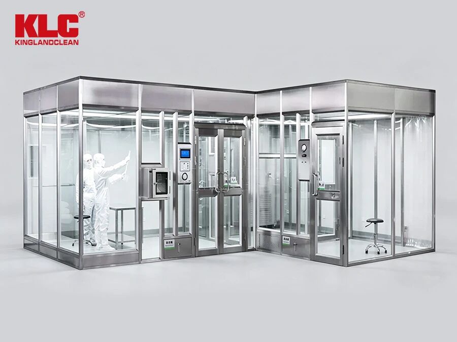
1. The Mobile Cleanroom: A "Clean Booth" on Wheels
Traditional cleanrooms are static. Once built, they are nearly impossible to relocate. For aerospace manufacturers dealing with bulky fuselage sections or wing assemblies, Portable Softwall Cleanrooms offer a dynamic alternative. These structures are essentially giant, sealed tents made of durable PVC curtains, supported by a rigid aluminum frame.
·Mobility and Flexibility: Unlike permanent walls, these Clean Booth structures can be disassembled and moved to wherever the large workpiece is located. This is crucial for "just-in-time" assembly lines where the component cannot be moved to the cleanroom; instead, the cleanroom comes to the component.
·The LAF Advantage: Within these large enclosures, Laminar Air Flow (LAF) is maintained using FFU (Fan Filter Unit). Specifically, Ceiling Suspended Laminar Air Flow systems ensure that HEPA-filtered air flows uniformly downward, sweeping contaminants away from the sensitive aerospace hardware.
·Cost-Effective Scalability: Building a permanent ISO 5 room for a single large component is expensive. A Portable Clean Room Box or Clean Booth allows manufacturers to create a "Mini-Environment" around the specific work area, drastically reducing the volume of air that needs conditioning and filtration.
By utilizing a Softwall structure, engineers achieve the necessary Cleanliness Scale without the massive capital expenditure of a fixed facility.
2. Structural Stability: Engineering for Large Spans
When dealing with large aerospace components, the cleanroom itself must be stable enough not to interfere with precision assembly. The challenge is maintaining structural rigidity over large spans without obstructing the workflow.
The Frame: The skeleton of a Portable Softwall Cleanrooms is typically made of anodized aluminum. This provides high strength with low weight. For extra stability in large configurations, manufacturers often use thicker extrusions or diagonal bracing to prevent sway during LAF operation.
Maintaining Pressure: A critical factor in structural integrity is Clean Room Pressure Control. The enclosure must maintain a positive pressure (typically 10-15 Pa differential) to keep unfiltered air out. The Softwall curtains must be tightly sealed at the floor and around the frame to prevent "breathing" or fluttering, which could disturb the Unidirectional Air Flow.
Access Without Compromise: Large components need large entry points. This is solved by using oversized Pass Boxes or Air Showers. In some cases, the entire side of the Clean Booth can be unzipped or rolled up for crane access, then resealed. For personnel, Dynamic Pass Boxes or airlocks allow technicians to enter the Sterile Room without causing a pressure dump.
The stability of these structures ensures that the Vertical Air Flow remains undisturbed, even when heavy machinery is moving nearby.
3. Integration with Aerospace Assembly Lines
The true test of a Portable Clean Room is how well it integrates with the existing factory floor. Aerospace assembly is a complex ballet of robotics, human technicians, and sensitive electronics.
Targeted Filtration: Instead of filtering the entire hangar, theMini-Environmentstrategy focuses on the "Critical Process Area." By placing the Clean Booth directly over the assembly point, you can utilize HEPA Filtered Air Showers at the entry points to scrub particles from tools and components before they enter the main chamber.
Essential Equipment: A standard setup includes FFU (Fan Filter Unit) for air circulation, Pass Through Boxesfor material transfer, and often a Down Flow Clean Bench for delicate electronics calibration.
Real-World Application: Imagine assembling a satellite dish or a section of a jet engine nacelle. The component sits on the floor. Technicians roll a Mobile LAF unit over it. The Ceiling Suspended Laminar Air Flow kicks in, creating a bubble of ISO 5 purity. The structure is stable, mobile, and maintains perfect Clean Room Air Pressure throughout the process.
Pro Tip: When sourcing these systems, look for suppliers offering Turnkey Modular Kits that include the FFU (Fan Filter Unit), lighting, and pressure monitoring systems all pre-integrated.
Conclusion: The Future of Flexible Manufacturing
For the aerospace industry, the days of being locked into a fixed cleanroom are over. Portable Softwall Cleanrooms provide the perfect blend of mobility, structural stability, and high-level filtration.
By focusing on Modular design and precise Pressure Control, these units allow large-scale components to be assembled in a controlled environment, regardless of their size. Whether you call it a Clean Booth, a Portable Clean Room, or a Mini-Environment, this technology is the key to the future of flexible, high-precision aerospace manufacturing.
In the world of controlled environments, every component matters. A clean booth is designed to maintain a specific level of air cleanliness, and its lighting system is no exception. The choice between a standard light fixture and a specialized purification lamp can significantly impact the overall integrity of the space. Let's explore why a dust-free purification lamp is not just an accessory, but a necessity for maintaining a pristine environment.
1. The Battle Against Particle Generation: Dust Accumulation
The primary function of a clean booth is to minimize airborne particulates. Ordinary lighting fixtures can work against this goal.
·Particle Traps: Standard lamps often have crevices, seams, and exposed screws that act as perfect traps for dust and other contaminants. Over time, these particles can accumulate and eventually be released into the controlled environment, compromising its cleanliness.
·Material Shedding: The materials used in conventional fixtures may not be designed for cleanroom use. They can degrade, flake, or shed microscopic particles, contributing to the very contamination the clean booth is meant to prevent.
·Cleaning Challenges: The complex surfaces of regular lights make them difficult to clean thoroughly. In contrast, a purification lamp is designed with a smooth, seamless surface that prevents dust from settling and allows for easy, effective cleaning, ensuring the environment remains free of contaminants.
2. Mastering Airflow: Minimizing Turbulence
Airflow is the lifeblood of a clean booth. It's designed to sweep particles away from the critical workspace. The wrong light fixture can disrupt this carefully managed flow.
·Disrupting Laminar Flow: A standard light fixture, with its bulky shape and uneven surfaces, acts as an obstacle. It disrupts the smooth, unidirectional laminar flow of filtered air, creating turbulent eddies. These eddies can cause particles to swirl and settle on products or surfaces instead of being carried away to the filters.
·Aerodynamic Design: Purification lamps are engineered with cleanroom standards in mind. Their streamlined, low-profile design minimizes interference with the airflow, allowing the filtered air to move smoothly across the workspace. This ensures that the air filtration system works as intended, maintaining the required cleanliness class.
·Integrated Systems: In many cases, these specialized lamps are designed to be integrated seamlessly with the ceiling grid and HEPA filter modules, creating a uniform ceiling that supports, rather than hinders, the cleanroom airflow.
3. Holistic Cleanliness: Protecting the Entire Environment
Choosing the right lighting is about more than just the fixture itself; it's about protecting the entire controlled environment and the processes within it.
·Preventing Cross-Contamination: In applications like a plant tissue culture lab or a dispensing booth, preventing cross-contamination is critical. A light fixture that harbors dust or microbes can become a source of contamination, jeopardizing sensitive experiments or products. A sealed purification lamp eliminates this risk.
·Maintaining Pressure Differentials: While seemingly unrelated, a well-sealed light fixture contributes to the overall integrity of the clean room pressure envelope. Leaky or poorly designed fixtures can create unintended air paths, making it harder to maintain the critical positive or negative pressure required for the space to function correctly.
·Supporting Critical Applications: Whether it's a clean bench for electronics assembly or a laminar flow clean bench for pharmaceutical work, the lighting must support the application's stringent requirements. A purification lamp is an integral part of the system, ensuring that the light source itself does not become the weakest link in the chain of contamination control.
In the highly regulated world of pharmaceuticals, maintaining the integrity of the cold chain is non-negotiable. A critical, yet often overlooked, component in this ecosystem is the pass box. Specifically, when bridging the gap between ambient environments and freezing cold storage, the challenge of condensation becomes a significant hurdle. To combat this, advanced engineering focusing on thermal barriers and active heating is essential.
Here is how modern pass box designs address these challenges to ensure compliance and safety.
1. The Challenge of Thermal Bridges and Condensation
When a pass box is installed between a warm corridor and a sub-zero cold room, the temperature differential creates a severe risk of condensation and frost. This moisture is not just a nuisance; it is a contamination risk that can compromise sterile products.
The Physics of Cold Transfer: Without proper insulation, the outer shell of the transfer unit can reach the dew point, causing water to form on the exterior.
Material Selection: To mitigate this, manufacturers often utilize specific grades of stainless steel and thermal breaks. This aligns with the broader industry demand for a dynamic stainless steel pass box, which offers durability and resistance to thermal shock.
Sealing Integrity: Just as a stainless steel pass box ensures a hermetic seal to maintain pressure differentials, the glazing must be equally robust to prevent thermal leakage.
2. Advanced Glazing: The Hollow Glass Solution
One of the most effective passive technologies to prevent heat transfer is the use of specialized glazing. Standard glass acts as a conductor, but modern solutions have evolved.
Insulation Properties: Utilizing hollow glass (often referred to as double glazing in other contexts) creates a buffer zone of air or inert gas between panes. This significantly reduces the U-value (thermal transmittance).
Visual Clarity: For operators, visibility is key. Hollow glass prevents the internal fogging that obscures the view, allowing staff to verify the transfer of goods without opening the doors.
Structural Integrity: This glazing is often paired with robust framing, similar to the construction found in a dynamic pass box, ensuring the unit remains airtight even under pressure differentials.
3. Active Heating and Electrical Integration
Passive insulation is often not enough for extreme temperature differences (e.g., -20°C to +20°C). Active heating elements are required to keep the surface temperature of the glass and frame above the dew point.
Heated Glass: Integrating heating wires or coatings into the glass prevents condensation formation entirely.
Electrical Requirements: These units require reliable power. The integration of these systems often parallels the complexity of other cleanroom equipment, such as an esp filter (Electrostatic Precipitator) or a chemical filter unit, which also require specific electrical setups for ionization or fan operation.
Control Systems: Modern units feature digital controllers to maintain the exact surface temperature, ensuring energy efficiency while preventing "sweating" on the pass box frame.
Conclusion
In pharmaceutical logistics, the margin for error is zero. Whether utilizing a standard pass box or a complex dynamic pass box, the integration of hollow glass and active heating technologies is not a luxury—it is a necessity. By preventing condensation, these technologies protect product purity and ensure that the cold chain remains unbroken.